RTC (Real Time Clock)
This page explains how to connect an RTC module to the Pico board.
About RTC Module
An RTC module is hardware that keeps track of real-time date and time.
If you read RP2040 Datasheet, you will find that the RP2040 microcontroller has a built-in RTC module. However, this built-in RTC does not have a backup battery, so it loses the date and time when power is lost. Therefore, it is not practical for use in applications where maintaining accurate time is important.
The practical way to use RTC is to connect an RTC module with a backup battery to the Pico board. This allows the date and time to be retained regardless of the Pico board's power state.
The DS3231 is a commonly used RTC module for electronics projects, as it can be connected via I2C. There is also a cheaper DS1307, but it can drift by several seconds per day, so the DS3231 is recommended for its higher accuracy.
The DS3231 module I purchased from Amazon looks like this:
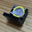
It comes with a backup battery pre-installed and has a compact shape. The signal names printed on the board can be confusing, but they correspond as follows:
| Board Label | Signal Name |
|---|---|
+ |
VCC (3.3V) |
D |
I2C SDA |
C |
I2C SCL |
- |
GND |
There is also a cheaper RTC module named DS1307, but it can drift by several seconds per day, so the more accurate DS3231 is recommended. The DS1307 also shares the same I2C address and data format as the DS3231, so it should work similarly when connected to the Pico board.
Sample Project
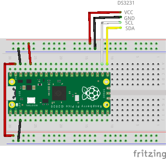
Wiring
The breadboard wiring image is as follows:
Building and Flashing the Program
Create a new Pico SDK project named rtctest. Check Console over UART and/or Console over USB in Stdio support.
Create Pico SDK Project
- In VSCode, run
>Raspberry Pi Pico: New Pico Projectin the command palette. -
In the dialog below, select
C/C++.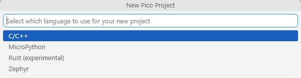
-
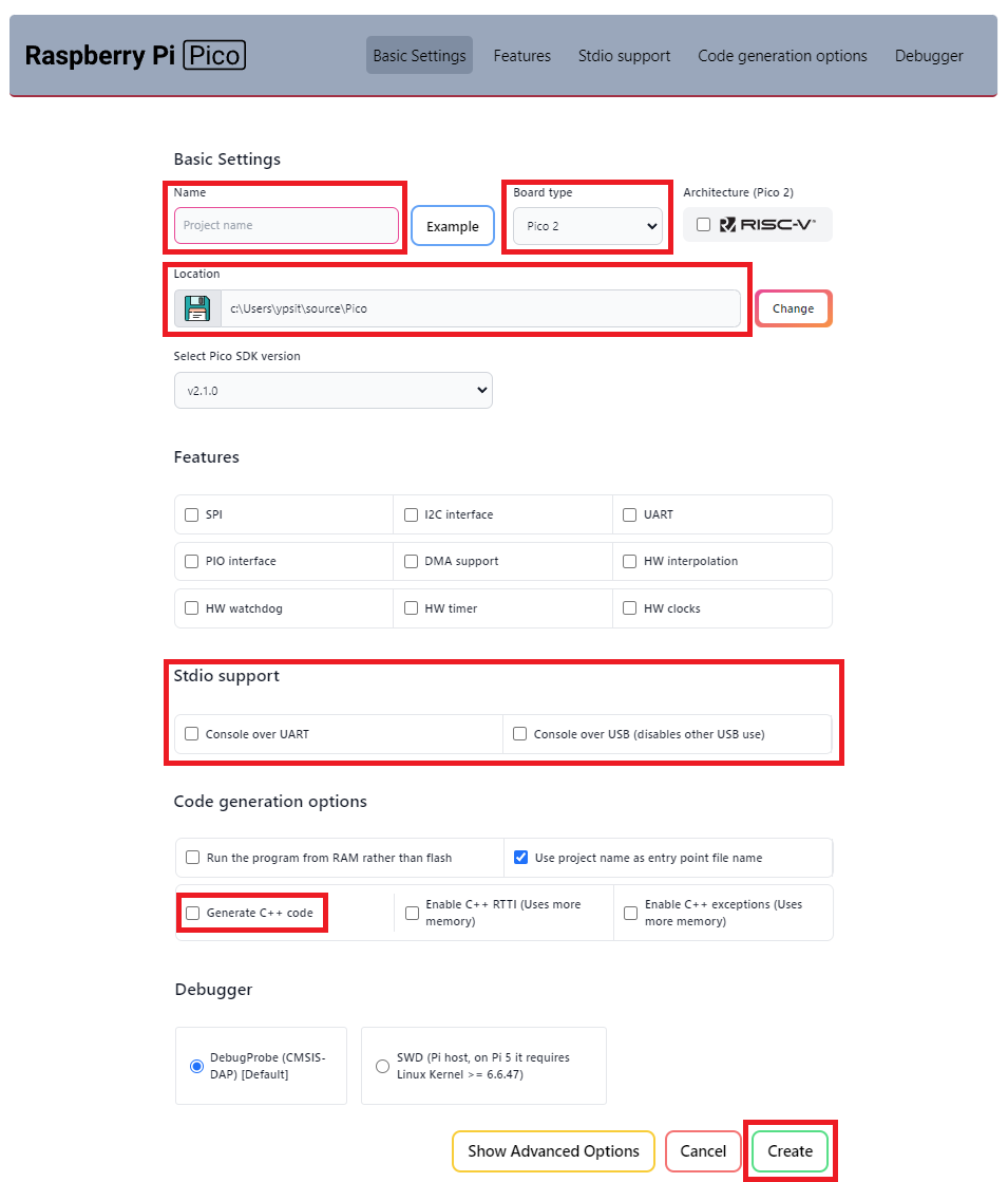
Create a project with the following settings:
- Name ... Enter the project name.
- Board type ... Select your board type.
- Location ... Select the parent directory where the project directory will be created.
- Stdio support ... Check
Console over UARTand/orConsole over USBfor stdio. DON'T checkConsole over USBwhen you use LABOPlatform or other USB features because they conflict with each other. - Code generation options ... Check
Generate C++ code.
Clone the pico-jxglib repository from GitHub so the direcory structure looks like this:
Clone the Repository
Change the current directory to the parent directory where you want to clone the pico-jxglib repository and run the following commands:
$ git clone https://github.com/ypsitau/pico-jxglib.git
$ cd pico-jxglib
$ git submodule update --init --recursive
pico-jxglib is updated almost daily. If you've already cloned it, run the following command in the pico-jxglib directory to get the latest version:
A directory from a Git repository can safely be moved to another location even after cloning.
Add the following lines to the end of CMakeLists.txt:
target_link_libraries(rtctest jxglib_RTC_DS3231)
add_subdirectory(${CMAKE_CURRENT_LIST_DIR}/../pico-jxglib pico-jxglib)
Edit rtctest.cpp as follows:
#include <stdio.h>
#include "pico/stdlib.h"
#include "jxglib/GPIO.h"
#include "jxglib/RTC/DS3231.h"

using namespace jxglib;

int main()
{
    ::stdio_init_all();
    ::i2c_init(i2c0, 400'000);
    GPIO16.set_function_I2C0_SDA().pull_up();
    GPIO17.set_function_I2C0_SCL().pull_up();
    RTC::DS3231 rtc(i2c0);
    for (;;) {
        DateTime dt;
        RTC::Get(&dt);
        ::printf("%04d-%02d-%02d %02d:%02d:%02d\n", dt.year, dt.month, dt.day, dt.hour, dt.min, dt.sec);
        ::sleep_ms(1000);
    }
}
After building the project by pressing F7, you can find the generated UF2 file in the build directory. Connect your Pico to the computer using a USB cable while holding the BOOTSEL button, and it will appear as a mass storage device, to which you can copy the generated UF2 file to flash it.
Running the Program
The program prints the current date and time every second. The output looks like this: