File System on SD Card
SD cards are familiar storage devices used in smartphones and are easily available at convenience stores. While it may seem simple to connect them to embedded devices, it can actually be tricky. This section explains how to connect SD cards and important points about the software.
How to Connect SD Cards
For details on how to connect and control SD cards, see the following site:
When connecting an SD card, keep the following in mind:
- The power supply for the SD card should be 3.3V.
- The signal level for the SD card is 3.3V. Since this matches the Pico board, you can connect directly.
- For all signal lines except clock, you need to pull up with a 10kΩ resistor (connect the signal line to VCC through a resistor).
The interface circuit for SD cards is built into the card itself, so you can connect the SD card pins directly to the Pico board. However, for removable media, you will likely use an SD card reader module with a card slot. The type of module and connection method, as well as the presence or absence of pull-up resistors and voltage regulators, varies, so be careful.
Below is a summary of the power supply voltage, pull-up resistors, and signal levels for SD card reader modules (mainly purchased from Amazon):
| Appearance | Notes |
|---|---|
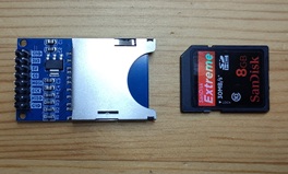 |
Standard SD card module. Both 5V and 3.3V power pins are available. If using 5V, a voltage regulator drops it to 3.3V for the SD card. All signal lines have 10kΩ pull-up resistors, so no external pull-ups are needed. Signal level is 3.3V; for 5V systems, a level shifter is required. |
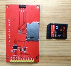 |
SD card slot on TFT LCD ILI9341. Power is supplied from the TFT LCD connector at 3.3V. External pull-up resistors are required1. Signal level is 3.3V; for 5V systems, a level shifter is required. |
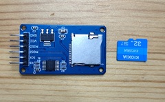 |
microSD card module. Power supply is 5V; a voltage regulator drops it to 3.3V for the SD card. No external pull-ups are needed. A buffer (74HC125) is included for the signal lines, allowing connection to both 3.3V and 5V systems. |
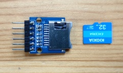 |
microSD card module. Power supply is 3.3V. All signal lines have 10kΩ pull-up resistors, so no external pull-ups are needed. Signal level is 3.3V; for 5V systems, a level shifter is required. |
About SD Card Drivers
SD cards have two modes: SPI mode and SDIO mode. SPI mode connects the SD card via an SPI interface, while SDIO mode uses the card's native interface. SDIO is faster and can fully utilize the SD card's capabilities, but there are very few examples of it working on the Pico board. pico-jxglib supports the well-documented SPI mode.
Although SD cards have built-in interface circuits, the details can vary slightly between cards. Therefore, even if you create a driver, you need to test it with various SD cards to ensure practical usability. In pico-jxglib, the SD card driver is based on the MicroPython SD card driver, rewritten in C++. Thanks to MicroPython for their work.
Creating a Project
From the VSCode command palette, run >Raspberry Pi Pico: New Pico Project and create a project with the following settings. For details on creating a Pico SDK project, building, and writing to the board, see "Getting Started with Pico SDK".
- Name ... Enter the project name. In this example, enter
fs-media. - Board type ... Select the board type.
- Location ... Select the parent directory where the project directory will be created.
- Stdio support ... Select the port (UART or USB) to connect Stdio. If using USB storage, be sure to disconnect the USB check to avoid conflicts.
- Code generation options ... Check
Generate C++ code
The project directory and pico-jxglib directory configuration is assumed to be as follows:
Below, we will edit the CMakeLists.txt and source files to create the program.
Program
Create a program that monitors the connection of the SD card and displays the directory listing when the connection is detected.
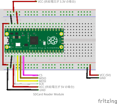
The breadboard wiring image is as follows. Use the SD card reader module and connect the power supply to 3.3V or 5V. If necessary, connect a 10kΩ pull-up resistor to the signal lines.
Add the following line to the end of CMakeLists.txt:
target_link_libraries(fs-media jxglib_FAT_SDCard)
add_subdirectory(${CMAKE_CURRENT_LIST_DIR}/../pico-jxglib pico-jxglib)
jxglib_configure_FAT(fs-media FF_VOLUMES 1)
Edit the source file as follows:
#include "pico/stdlib.h"
#include "jxglib/FAT/SDCard.h"

using namespace jxglib;

int main()
{
    ::stdio_init_all();
    GPIO2.set_function_SPI0_SCK();
    GPIO3.set_function_SPI0_TX();
    GPIO4.set_function_SPI0_RX();
    FAT::SDCard drive("Drive:", spi0, 10'000'000, {CS: GPIO5});
    bool connectedFlag = false;
    for (;;) {
        if (connectedFlag) {
            if (!drive.CheckMounted()) {
                ::printf("SD Card disconnected.\n");
                connectedFlag = false;
            }
        } else if (drive.Mount()) {
            ::printf("SD Card connected.\n");
            connectedFlag = true;
            FS::Dir* pDir = FS::OpenDir("Drive:/");
            if (pDir) {
                FS::FileInfo* pFileInfo;
                while (pFileInfo = pDir->Read()) {
                    ::printf("%-16s%d\n", pFileInfo->GetName(), pFileInfo->GetSize());
                    delete pFileInfo;
                }
                pDir->Close();
                delete pDir;
            }
        }
        Tickable::Tick();
    }
}
FAT::SDCard instance generates a FAT file system. The constructor details are as follows:
FAT::SDCard(const char* driveName, spi_inst_t* spi, uint baudrate, const jxglib::SDCard::PinAssign& pinAssign)drivename: Path name to use for the drive. You can specify any string.spi: SPI interface pointer. Specifyspi0orspi1.baudrate: SPI clock frequency.pinAssign: GPIO pin to use for CS (Chip Select).
File system API details are in "Implementing a File System on the Pico Board with pico-jxglib and Using Flash Memory Fully".
-
In my tests, some SD cards worked without pull-up resistors, but depending on the card type, pull-ups may be required. If it doesn't work, check for the presence of pull-up resistors. ↩