Skip to content

Camera - OV7670

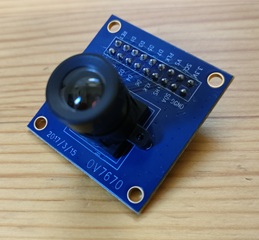
The OV7670 is a VGA resolution (640x480) camera module developed by Omnivision. It is a very popular camera module, widely used in electronics projects due to its low cost (about $5 USD). However, there are not many general-purpose libraries available, so integrating it into your own project usually requires some programming skill.

ov7670.jpg

With pico-jxgLABO, you can set up the OV7670 camera module using commands, making it easy to test and experiment with the camera without writing code. You can change the resolution and adjust parameters via commands, so you can try things out before moving on to more advanced programming.

This article demonstrates the following experiments using this camera module:

Experiment 1: Start a camera app on a host PC (Windows) connected to the Pico board via USB, and stream video from the OV7670 camera module. This experiment only requires the OV7670 camera module, Pico board, and host PC.

Experiment 2: Add a TFT LCD display module (ST7789) and display the camera image in real time on the display.

The host PC for development and testing is assumed to be Windows.

Demo Video

About the OV7670 Camera Module

For modules without FIFO memory, the OV7670 outputs image data via an 8-bit parallel data bus, synchronized by a clock. Register settings and configuration are performed via the I2C interface.

The OV7670 camera module signals are as follows:

Signal Name Description
3.3V, GND Power supply
PWDN Power down control. Connect to GND for normal operation
RESET Reset input. Active low. Connect to 3.3V for normal operation
D0-D7 8-bit parallel data bus
XCLK External clock input. Usually supplied with a 24 MHz square wave
PCLK Pixel clock output. Pulses for each pixel
HREF Horizontal reference signal. Pixel data is valid while this is active
VSYNC Vertical sync signal. Indicates the start of a frame
SDA I2C data line
SCL I2C clock line

Even without register configuration, supplying a clock to XCLK will start image data output. The image data acquisition flow is as follows:

  1. A VSYNC pulse indicates the start of a frame. Detect the transition from Low to High on VSYNC.
  2. While HREF is High, read D0-D7 data on each rising edge of PCLK (Low to High transition). Pixel data is invalid while HREF is Low.
  3. Repeat step 2 for the number of pixels in a frame.

Official datasheets are not always available from the manufacturer. The following PDF files were referenced for this article1. The Implementation Guide is especially useful, as it categorizes the register groups by function.

▶️ Advanced Information Preliminary Datasheet ▶️ OV7670 Implementation Guide (V1.0)

Note that these documents are incomplete and some important information is missing. For example, to get color images, you need to set a register: "set register 0xB0 to 0x84". However, the documents do not explain what register 0xB0 controls or what the value 0x84 means. For these details, you may need to refer to code written by previous developers who likely reverse-engineered the device.

Connecting the OV7670 Camera Module

The OV7670 camera module connects to the Pico board using the I2C interface and several GPIO pins. Refer to the wiring example below:

ov7670-wiring.png

You can customize the GPIO pins via commands. Keep the following points in mind:

  • Connect 3.3V and GND to power
  • Connect PWDN to GND and RESET to 3.3V
  • Connect the 8 data lines D0 to D7 to consecutive GPIO pins
  • Connect XCLK, PCLK, HREF, and VSYNC to any GPIO pins
  • Connect SDA and SCL to either I2C0 or I2C1 on the Pico board

The signal lines carry high-frequency currents, with XCLK reaching up to 24 MHz. Shorter wires are better, but in practice, even 16 cm jumper wires worked fine in my tests.

ov7670-wiring-photo.jpg

Run the following commands to set up the I2C interface and camera module:

L:>i2c0 -p 16,17 --baudrate:100000
L:>camera-ov7670 setup {i2c:0 d0:2 xclk:10 pclk:11 href:12 vsync:13}
  • The i2c0 command sets I2C0 to GPIO16 (SDA) and GPIO17 (SCL) at 100 kHz.
  • The camera-ov7670 setup command specifies the connection pins for the OV7670 camera module. I2C0 is selected for I2C. D0 is connected to GPIO2, and D1-D7 are automatically assigned to GPIO3-GPIO9. XCLK, PCLK, HREF, and VSYNC are connected to GPIO10, GPIO11, GPIO12, and GPIO13, respectively.

Now the OV7670 camera module is ready to use. Run the dump subcommand of camera-ov7670 to check the camera module's register settings:

L:/>camera-ov7670 dump
00  3C 80 80 00 01 0B 61 40 9D 00 76 73 04 00 01 02
10  7F 01 04 EF 20 02 00 11 61 03 7B 00 7F A2 04 00
20  04 02 01 00 75 63 A5 80 80 07 00 00 80 00 00 61
30  08 30 80 08 11 1A 00 3F 01 00 00 08 68 C0 19 00
40  11 08 00 14 F0 45 61 51 79 00 00 01 00 00 00 80
50  80 00 22 5E 80 00 40 80 1E 00 00 01 00 00 00 F0
60  F0 F0 00 00 04 20 05 80 80 01 80 4A 0A 55 11 9A
70  3A 35 11 F1 11 0F C1 10 00 00 20 1C 28 3C 55 68
80  76 80 88 8F 96 A3 AF C4 D7 E8 00 00 00 0F 00 00
90  00 00 00 00 04 08 01 01 10 40 40 20 00 99 7F 78
A0  68 03 02 00 00 05 DF DF F0 90 94 07 00 00 00 00
B0  84 04 00 82 00 20 00 66 00 06 00 00 00 00 00 00
C0  00 00 00 00 00 00 00 00 06 CE

i2c0 -p 16,17 --baudrate:100000

Experiment 1: Video Streaming to Host PC

Start the camera app on a host PC (Windows) connected to the Pico board via USB, and display video streaming from the OV7670 camera module.

  1. Connect the host PC and Pico board with a USB cable.

  2. Create a .startup file in the root directory of the Pico board's L: drive with the following content. The L: drive appears as a USB mass storage device on the host PC, so you can create this file with a text editor on your PC.

text:.startup usbdev-video-transmitter setup i2c0 -p 16,17 --baudrate:100000 camera-ov7670 setup {i2c:0 d0:2 xclk:10 pclk:11 href:12 vsync:13}

The usbdev-video-transmitter setup command sets up the Pico board as a USB video device. The remaining commands set up the OV7670 camera module.

Unplug and replug the USB cable to reboot the Pico board. It should now be recognized as a USB video device.

  1. On the host PC, search for "Camera" in the taskbar and start the camera app. If recognized correctly, "pico-jxgLABO VideoTransmitter" will be displayed at startup.

windows-camera-app.png

If multiple camera devices are connected to the PC, a camera selection button will appear in the top right of the app. Switch to the screen showing "pico-jxgLABO VideoTransmitter".

windows-camera-app-select.png

  1. In the terminal, run the following command to start video streaming from the OV7670 camera module to the host PC:
L:>camera video-transmit-start

If the camera app displays video from the OV7670 camera module, it is working.

windows-camera-app-ov7670.png

Run the camera fps command to check the current frame rate:

L:>camera fps
6 fps

The screen size is set to QQVGA (160x120), but the USB transfer speed is a bottleneck, so the frame rate is only about 6 fps.

Experiment 2: Real-Time Display on TFT Display

Display the camera image in real time on an ST7789 TFT display module.

  1. Connect the OV7670 camera module and ST7789 TFT display module to the Pico board as shown below:

ov7670-st7789-wiring.png

ov7670-st7789-wiring-photo.jpg

  1. Run the following commands to set up the OV7670 camera module and ST7789 TFT display module:
L:>i2c0 -p 16,17 --baudrate:100000
L:>camera-ov7670 setup {i2c:0 d0:2 xclk:10 pclk:11 href:12 vsync:13}
L:>spi1 -p 14,15 --baudrate:50000000
L:>display-st7789 setup {spi:1 rst:18 dc:19 cs:20 bl:21 dir:rotate90}
  1. Test the TFT display by running the following command. If the entire screen turns red, the display is working:
L:>draw fill {color:red}
  1. Run the display-start subcommand of the camera command to display the OV7670 camera image on the TFT display in real time:
L:>camera display-start

Run the camera fps command to check the current frame rate:

L:>camera fps
27 fps

The maximum frame rate of the OV7670 is 30 fps, so this is nearly full speed.

When outputting to the TFT display module, you can also change the resolution. Use the resolution subcommand of camera-ov7670 to change to one of the following resolutions:

Resolution Name Pixels RAM Usage
qvga 320 x 240 153.6 kB
qqvga 160 x 120 38.4 kB
qqqvga 80 x 60 9.6 kB

For example, to change the resolution to QQVGA (160x120):

L:>camera-ov7670 resolution:qqvga

The maximum resolution of the OV7670 camera module is VGA (640x480), but the image data size is 614.4 kB, which exceeds the RAM size of the Pico board (Pico: 264 kB, Pico2: 520 kB), so it cannot be used.

Automating Initialization with a .startup File

The setup commands for the OV7670 camera module are a bit long, so you can put them in a .startup file to run them automatically when the board starts up.

Here is an example .startup file that sets up the USB video device, OV7670 camera module, and ST7789 TFT display module:

```text:.startup usbdev-video-transmitter setup

camera-ov7670 setup {i2c:0 d0:2 xclk:10 pclk:11 href:12 vsync:13}

spi1 -p 14,15 --baudrate:50000000 display-st7789 setup {spi:1 rst:18 dc:19 cs:20 bl:21 dir:rotate90}

### Setting Various Parameters

The `camera-ov7670` command allows you to set various parameters using subcommands. Use the `--help` option to see a list of available subcommands:

```text
L:/>camera-ov7670 --help
Usage: camera-ov7670 [OPTION]... [SUBCMD...]
Options:
 -h --help prints this help
Sub Commands:
 setup                              setup a OV7670 camera module with the given parameters:
                         {i2c:BUS d0:PIN xclk:PIN pclk:PIN href:PIN vsync:PIN [pwdn:PIN] [reset:PIN] [freq:FREQ]}
 reso:RESO                          gets/sets resolution: vga, qvga, qqvga, qqqvga
 format:FORMAT                      gets/sets format: rgb565, yuv422
 dump                               dumps all OV7670 registers
 ccir656:[on|off]                   enables/disables CCIR656 mode
 scale:[on|off]                     enables/disables scaling
 dcw:[on|off]                       enables/disables DCW
 color-bar:[on|off]                 enables/disables color bar
 agc:[on|off]                       enables/disables AGC
 awb:[on|off]                       enables/disables AWB
 aec:[on|off]                       enables/disables AEC
 mirror:[on|off]                    enables/disables mirror
 vflip:[on|off]                     enables/disables vertical flip
  :
  :

Here are some examples of main subcommands:

  • mirror: Enable/disable mirror (horizontal flip)
L:>camera-ov7670 mirror:on
  • vflip: Enable/disable vertical flip
L:>camera-ov7670 vflip:on
  • brightness: Set brightness (-127 to +127, default 0)
L:>camera-ov7670 brightness:-4
  • contrast: Set contrast (0 to 255, default 64)
L:>camera-ov7670 contrast:15
  • sharpness: Set sharpness (0 to 31, default 0)
L:>camera-ov7670 sharpness:7
  • awb, awb-red, awb-blue, awb-green: Enable/disable auto white balance (AWB) and set gain for each color (0 to 255, default 128). If awb is set to on, the gains are adjusted automatically. If set to off, the values specified by awb-red, awb-blue, and awb-green are used.
L:>camera-ov7670 awb:off
L:>camera-ov7670 awb-reds:120 awb-blue:140 awb-green:180