LVGL
This page explains how to use pico-jxglib to implement advanced GUIs on TFT LCDs using LVGL. A TFT LCD with a touchscreen can become a versatile input device.
About LVGL
LVGL is a library that enables advanced GUIs on embedded devices with limited resources. It can run on as little as a 16MHz CPU, 64KB of flash, and 16KB of RAM. On a Pico with a 125MHz CPU, 2MB of flash, and 264KB of SRAM, you have plenty of headroom!
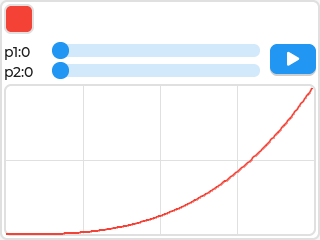
Despite its low resource requirements, LVGL offers very high expressive power. The following snapshot is from one of LVGL's sample programs:
 (from the LVGL documentation)
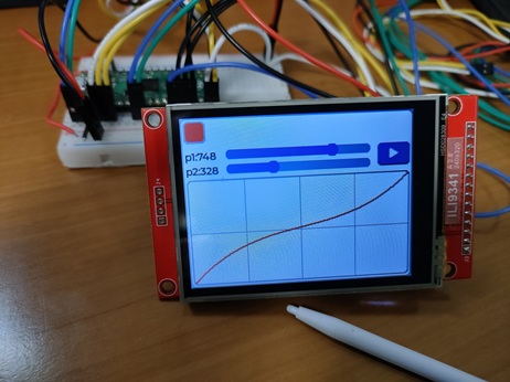
When you operate the sliders, a Bezier curve is drawn in real time on the graph, with the values as control points. Clicking the play button on the right animates the red square along the curve at a speed corresponding to the curve. You can see an actual animation here. It's amazing that you can implement exactly the same GUI on your own microcontroller!
What's even more impressive is that LVGL is not just for practical use, but also has a playful visual style. For example, when you click a button, you can add effects like a soft expansion. It's perfect for consumer-oriented UIs.
Porting to various platforms is also easy, following Connecting LVGL to Your Hardware. pico-jxglib benefits from this flexibility.
Example Project
Connect an ILI9341 with a touchscreen and run a program using LVGL. For devices without a touchscreen, you can simulate keyboard operations via Stdio. For using USB keyboards and mice with LVGL, see the following article:
https://zenn.dev/ypsitau/articles/2025-04-02-usbhost-keyboard-mouse#lvgl-%E3%81%A8-usb-%E3%82%AD%E3%83%BC%E3%83%9C%E3%83%BC%E3%83%89%E3%83%BB%E3%83%9E%E3%82%A6%E3%82%B9
Creating a Project
From the VSCode command palette, run >Raspberry Pi Pico: New Pico Project and create a project with the following settings. For details on creating a Pico SDK project, building, and writing to the board, see "Getting Started with Pico SDK".
- Name ... Enter the project name. In this example, enter
lvgltest. - Board type ... Select the board type.
- Location ... Select the parent directory where the project directory will be created.
- Stdio support ... Select the port (UART or USB) to connect Stdio.
- Code generation options ... Check
Generate C++ code
Assume the project directory and pico-jxglib are arranged as follows:
From here, edit CMakeLists.txt and the source file based on this project to create your program.
Building and Running the Sample Program
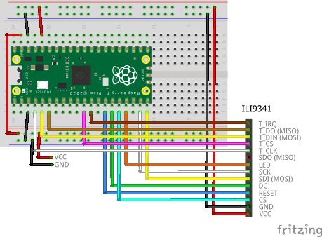
The breadboard wiring image is as follows:
Add the following lines to the end of CMakeLists.txt:
target_link_libraries(lvgltest jxglib_Display_ILI9341 jxglib_LVGL lvgl_examples)
add_subdirectory(${CMAKE_CURRENT_LIST_DIR}/../pico-jxglib pico-jxglib)
jxglib_configure_LVGL(lvgltest LV_FONT_MONTSERRAT_14)
The jxglib_configure_LVGL() function generates the lv_conf.h header file needed for building LVGL. List the macro variable names for the fonts you want to use as arguments. The first font specified becomes the default font.
Edit the source file as follows:
#include <stdio.h>
#include <examples/lv_examples.h>
#include "pico/stdlib.h"
#include "jxglib/Display/ILI9341.h"
#include "jxglib/LVGL.h"

using namespace jxglib;

int main()
{
    ::stdio_init_all();
    ::spi_init(spi0, 2 * 1000 * 1000);
    ::spi_init(spi1, 125 * 1000 * 1000);
    GPIO2.set_function_SPI0_SCK();
    GPIO3.set_function_SPI0_TX();
    GPIO4.set_function_SPI0_RX();
    GPIO14.set_function_SPI1_SCK();
    GPIO15.set_function_SPI1_TX();
    Display::ILI9341 display(spi1, 240, 320, {RST: GPIO10, DC: GPIO11, CS: GPIO12, BL: GPIO13});
    Display::ILI9341::TouchScreen touchScreen(spi0, {CS: GPIO8, IRQ: GPIO9});
    display.Initialize(Display::Dir::Rotate90);
    touchScreen.Initialize(display);
    //touchScreen.Calibrate(display);
    LVGL::Initialize();
    LVGL::Adapter lvglAdapter;
    lvglAdapter.EnableDoubleBuff().AttachDisplay(display).AttachTouchScreen(touchScreen);
    ::lv_example_anim_3();
    for (;;) {
        ::sleep_ms(5);
        ::lv_timer_handler();
    }
}
Program Explanation
The program's processing content is explained as follows:
Initialize SPI0 at 2MHz for the touchscreen and SPI1 at 125MHz for the TFT LCD.
GPIO2.set_function_SPI0_SCK();
GPIO3.set_function_SPI0_TX();
GPIO4.set_function_SPI0_RX();
GPIO14.set_function_SPI1_SCK();
GPIO15.set_function_SPI1_TX();
Assign GPIOs to the SPI0 and SPI1 signal lines.
Display::ILI9341 display(spi1, 240, 320, {RST: GPIO10, DC: GPIO11, CS: GPIO12, BL: GPIO13});
Display::ILI9341::TouchScreen touchScreen(spi0, {CS: GPIO6, IRQ: GPIO7});
display.Initialize(Display::Dir::Rotate90);
touchScreen.Initialize(display);
//touchScreen.Calibrate(display);
Assign SPI and GPIO to the TFT LCD and touchscreen parts, initializing them. The touchscreen's screen coordinates are mapped to preset values from the device's calibration, but the device-specific variations are still unknown. If the screen is too far off, call the Calibrate() function to calibrate.
Initialize LVGL.
LVGL::Adapter lvglAdapter;
lvglAdapter.EnableDoubleBuff().AttachDisplay(display).AttachTouchScreen(touchScreen);
Use LVGL::Adapter to connect the TFT LCD and touchscreen to LVGL. EnableDoubleBuff() enables double buffering, which increases drawing speed using DMA. However, it consumes 2 times the memory.
Call LVGL's sample program functions. Internally, widget creation and callback registration occur.
The main loop. ::lv_timer_handler() performs LVGL processing.
Various Sample Programs
The directory pico-jxglib/LVGL/lvgl/examples contains over 100 LVGL sample programs. We have prepared Pico SDK projects to run these easily.
The same ILI9341 is used. The breadboard wiring image is the same. Connect a USB-serial converter to the UART port (TX: GPIO0, RX: GPIO1) or connect via USB to the PC and start a serial terminal app (communication speed 115200bps).
In the directory pico-jxglib/LVGL/test-examples, open VSCode and build the project. Run the program and you'll see a screen like this:
--------
1:anim_1 52:style_5 103:keyboard_2
2:anim_2 53:style_6 104:label_1
3:anim_3 54:style_7 105:label_2
...
50:style_3 101:imagebutton_1 152:tileview_1
51:style_4 102:keyboard_1 153:win_1
Enter Number:
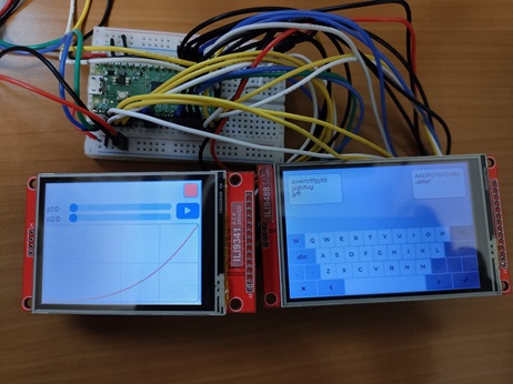
Displaying on Multiple LCDs
Create multiple LVGL::Adapter instances and connect each to a TFT LCD or touchscreen to display LVGL GUIs on multiple screens.
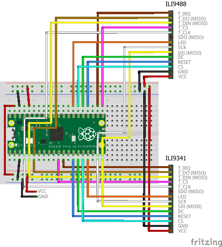
In this example, we connect ILI9341 and ILI9488. The breadboard wiring image is as follows:
Add the following lines to the end of CMakeLists.txt:
target_link_libraries(lvgltest jxglib_Display_ILI9341 jxglib_Display_ILI9488 jxglib_LVGL lvgl_examples)
add_subdirectory(${CMAKE_CURRENT_LIST_DIR}/../pico-jxglib pico-jxglib)
jxglib_configure_LVGL(lvgltest LV_FONT_MONTSERRAT_14)
Edit the source file as follows:
#include <stdio.h>
#include <examples/lv_examples.h>
#include "pico/stdlib.h"
#include "jxglib/Display/ILI9341.h"
#include "jxglib/Display/ILI9488.h"
#include "jxglib/LVGL.h"
using namespace jxglib;
int main()
{
::stdio_init_all();
::spi_init(spi0, 2 * 1000 * 1000);
::spi_init(spi1, 125 * 1000 * 1000);
GPIO2.set_function_SPI0_SCK();
GPIO3.set_function_SPI0_TX();
GPIO4.set_function_SPI0_RX();
GPIO14.set_function_SPI1_SCK();
GPIO15.set_function_SPI1_TX();
Display::ILI9341 display1(spi1, 240, 320, {RST: GPIO10, DC: GPIO11, CS: GPIO12, BL: GPIO13});
Display::ILI9488 display2(spi1, 320, 480, {RST: GPIO18, DC: GPIO19, CS: GPIO20, BL: GPIO21});
Display::ILI9341::TouchScreen touchScreen1(spi0, {CS: GPIO8, IRQ: GPIO9});
Display::ILI9488::TouchScreen touchScreen2(spi0, {CS: GPIO16, IRQ: GPIO17});
display1.Initialize(Display::Dir::Rotate90);
display2.Initialize(Display::Dir::Rotate90);
touchScreen1.Initialize(display1);
touchScreen2.Initialize(display2);
LVGL::Initialize();
LVGL::Adapter lvglAdapter1;
lvglAdapter1.AttachDisplay(display1).AttachTouchScreen(touchScreen1);
LVGL::Adapter lvglAdapter2;
lvglAdapter2.SetPartialNum(20).AttachDisplay(display2).AttachTouchScreen(touchScreen2);
lvglAdapter1.SetDefault();
::lv_example_anim_3();
lvglAdapter2.SetDefault();
::lv_example_keyboard_1();
for (;;) {
    ::sleep_ms(5);
    ::lv_timer_handler();
}
}
LVGL::Adapter instances have SetDefault() functions. After calling SetDefault(), all LVGL function calls are directed to that adapter. SetPartialNum() specifies how many times LVGL divides the screen. The more the number, the more divisions, and the smaller the buffer size. Usually, 10 divisions are set, but in this example, we have two LCDs and an additional ILI9488 with a large screen and 3 bytes per pixel, exceeding the Pico's RAM capacity. We increase the number of divisions to save memory.
Stdio Input
LVGL operations are typically touchscreens, but keyboard input is also possible. Here, we explain how to simulate keyboard input from Stdio.
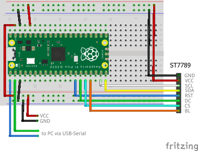
The TFT LCD uses ST7789. The breadboard wiring image is as follows:
Add the following lines to the end of CMakeLists.txt:
target_link_libraries(lvgltest jxglib_Display_ST7789 jxglib_LVGL lvgl_examples)
add_subdirectory(${CMAKE_CURRENT_LIST_DIR}/../pico-jxglib pico-jxglib)
jxglib_configure_LVGL(lvgltest LV_FONT_MONTSERRAT_14)
Edit the source file as follows:
#include <stdio.h>
#include <examples/lv_examples.h>
#include "pico/stdlib.h"
#include "jxglib/Stdio.h"
#include "jxglib/Display/ST7789.h"
#include "jxglib/LVGL.h"

using namespace jxglib;

int main()
{
    ::stdio_init_all();
    ::spi_init(spi1, 125 * 1000 * 1000);
    GPIO14.set_function_SPI1_SCK();
    GPIO15.set_function_SPI1_TX();
    Display::ST7789 display(spi1, 240, 320, {RST: GPIO10, DC: GPIO11, CS: GPIO12, BL: GPIO13});
    display.Initialize(Display::Dir::Rotate90);
    LVGL::Initialize();
    LVGL::Adapter lvglAdapter;
    lvglAdapter.EnableDoubleBuff().AttachDisplay(display).AttachKeyboard(Stdio::GetKeyboard());
    ::lv_example_keyboard_1();
    for (;;) {
        ::sleep_ms(5);
        ::lv_timer_handler();
    }
}
PgUp and PgDn move the focus. Enter clicks the focused widget.