RTC (Real Time Clock)
In this page, we will connect an RTC (Real Time Clock) module to the Pico board.
By connecting an RTC module, you can accurately obtain the current time and record timestamps when creating or updating files. The RTC module is used via the I2C interface.
About RTC Module
An RTC module is hardware that keeps track of real-time date and time.
If you read RP2040 Datasheet, you will find that the RP2040 microcontroller has a built-in RTC module. However, this built-in RTC does not have a backup battery, so it loses the date and time when power is lost. Therefore, it is not practical for use in applications where maintaining accurate time is important.
The practical way to use RTC is to connect an RTC module with a backup battery to the Pico board. This allows the date and time to be retained regardless of the Pico board's power state.
The DS3231 is a commonly used RTC module for electronics projects, as it can be connected via I2C. There is also a cheaper DS1307, but it can drift by several seconds per day, so the DS3231 is recommended for its higher accuracy.
The DS3231 module I purchased from Amazon looks like this:

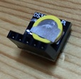
It comes with a backup battery pre-installed and has a compact shape. The signal names printed on the board can be confusing, but they correspond as follows:
| Board Label | Signal Name |
|---|---|
+ |
VCC (3.3V) |
D |
I2C SDA |
C |
I2C SCL |
- |
GND |
There is also a cheaper RTC module named DS1307, but it can drift by several seconds per day, so the more accurate DS3231 is recommended. The DS1307 also shares the same I2C address and data format as the DS3231, so it should work similarly when connected to the Pico board.
Device Connection and Operation Check
The DS3231 RTC module is connected via the I2C interface. You can use either I2C0 or I2C1 on the Pico board, and the pin layout can be freely set with commands. Here, we use I2C0 and connect as follows:
| DS3231 | Pico Pin No. | GPIO | Function |
|---|---|---|---|
| VCC | 36 | 3V3 | |
| GND | 8 | GND | |
| SDA | 11 | GPIO8 | I2C0 SDA |
| SCL | 12 | GPIO9 | I2C0 SCL |
The wiring diagram is shown below. There are multiple GND pins on the Pico board, so you can connect to any of them.

Run the following command to set the GPIO assignment for I2C0 to GPIO8 (I2C0 SDA) and GPIO9 (I2C0 SCL). The appropriate function assignment is done automatically, so the order does not matter.
Scan the devices connected to the I2C bus to confirm that the RTC module is connected correctly. The DS3231 uses I2C address 0x68.
L:/>i2c0 scan
Bus Scan on I2C0
0 1 2 3 4 5 6 7 8 9 A B C D E F
00 -- -- -- -- -- -- -- -- -- -- -- -- -- -- -- --
10 -- -- -- -- -- -- -- -- -- -- -- -- -- -- -- --
20 -- -- -- -- -- -- -- -- -- -- -- -- -- -- -- --
30 -- -- -- -- -- -- -- -- -- -- -- -- -- -- -- --
40 -- -- -- -- -- -- -- -- -- -- -- -- -- -- -- --
50 -- -- -- -- -- -- -- -- -- -- -- -- -- -- -- --
60 -- -- -- -- -- -- -- -- 68 -- -- -- -- -- -- --
70 -- -- -- -- -- -- -- -- -- -- -- -- -- -- -- --
Run the following command to set up the DS3231 RTC module:
This completes the setup of the DS3231 RTC module.
Run the rtc command to get the current time from the RTC module:
You can set the date and time on the RTC module by specifying the date and time as an argument to the rtc command:
If your Pico board is connected to Wi-Fi (see here), you can use the ntp command with the -r option to get the correct time from an NTP server and set it on the RTC module:
Let's create a file and check that the timestamp is recorded correctly: