Overview
In the article "Connecting USB Keyboard and Mouse to Pico Board with pico-jxglib", we connected a USB keyboard to the Pico board. This time, we'll use that to implement a command line editing feature on the Pico board, similar to readline used in Linux bash shells.
In addition to USB keyboards, you can also use tact switches and keyboard matrices as input devices, and command line editing is possible over serial communication with a PC.
Once you can edit input with a keyboard, the Pico board really feels like a standalone microcontroller. If the phrase "microcomputer monitor program" makes your heart skip a beat, you should definitely give this a try!
About the Command Line Editing Feature
The command line editing feature of pico-jxglib supports the following key operations:
| Ctrl Key | Single Key | Function |
|---|---|---|
Ctrl + P |
Up |
Show previous history entry |
Ctrl + N |
Down |
Show next history entry |
Ctrl + B |
Left |
Move cursor one character left |
Ctrl + F |
Right |
Move cursor one character right |
Ctrl + A |
Home |
Move cursor to the beginning of the line |
Ctrl + E |
End |
Move cursor to the end of the line |
Ctrl + D |
Delete |
Delete the character at the cursor |
Ctrl + H |
Back |
Delete the character before the cursor |
Ctrl + J |
Return |
Confirm the input |
Ctrl + K |
Delete from cursor to end of line | |
Ctrl + U |
Delete from before cursor to beginning of line |
When using a display connected to the Pico board, the following key operations are also supported:
| Ctrl Key | Single Key | Function |
|---|---|---|
PageUp |
Scroll rollback screen up by one line. Hold Shift for page scroll |
|
PageDown |
Scroll rollback screen down by one line. Hold Shift for page scroll |
Two Types of Terminal
The command line editing feature can be used with the following two types of Terminal:
Display::Terminal... Use a display connected to the Pico board for command line input. You can edit commands standalone on the Pico.Serial::Terminal... Use serial communication for command line input. You edit commands on a terminal software running on a host PC connected to the Pico.
For Display::Terminal, specify a display device such as ST7789 as the output, and set the input device as one of USBHost::Keyboard (USB keyboard), Stdio::Keyboard (keyboard input from host via Stdio), GPIO::Keyboard (switch input connected to GPIO), or GPIO::KeyboardMatrix (matrix switch input connected to GPIO).
graph TD
    subgraph Keyboard
        K1(USBHost::Keyboard)
        K2(Stdio::Keyboard)
        K3(GPIO::Keyboard)
        K4(GPIO::KeyboardMatrix)
    end
    subgraph Display
        D1(ST7789)
        D2(ST7735)
        D3(ILI9341)
        D4(ILI9488)
        D5(SSD1306)
    end
    Keyboard--"AttachKeyboard()"-->T(Display::Terminal)--"AttachDisplay()"-->Display
For Serial::Terminal, specify Stdio as the output1. Set the input device as one of USBHost::Keyboard, Stdio::Keyboard, GPIO::Keyboard, or GPIO::KeyboardMatrix.
graph TD
    subgraph Keyboard
        K1(USBHost::Keyboard)
        K2(Stdio::Keyboard)
        K3(GPIO::Keyboard)
        K4(GPIO::KeyboardMatrix)
    end
    subgraph Printable
        P1(Stdio)
    end
    Keyboard--"AttachKeyboard()"-->T(Serial::Terminal)--"AttachPrintable()"-->Printable
Example Project
Using Display::Terminal
Connect a keyboard and display to the Pico board to enable standalone command input. Many combinations are possible, so here are some examples.
Creating a Project for Display::Terminal
From the VSCode command palette, run >Raspberry Pi Pico: New Pico Project and create a project with the following settings. For details on creating a Pico SDK project, building, and writing to the board, see "Getting Started with Pico SDK".
- Name ... Enter the project name. In this example, enter
cmdedit-display-test. - Board type ... Select the board type.
- Location ... Select the parent directory where the project directory will be created.
- Stdio support ... Select the port (UART or USB) to connect Stdio, but USB cannot be selected for this program. Select only UART or leave both unchecked.
- Code generation options ... Check
Generate C++ code
Assume the project directory and pico-jxglib are arranged as follows:
From here, edit CMakeLists.txt and the source file based on this project to create your program.
USB Keyboard + TFT LCD (ST7789)
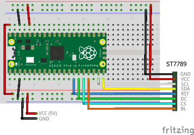
Connect the USB keyboard using a microB-TypeA adapter to the USB port (see here for details). The TFT LCD used is ST7789, but for other display devices, see "pico-jxglib and TFT LCD".
The breadboard wiring image is shown below. Note that the 5V power is connected to the Pico board's VBUS (pin 40).
Add the following lines to the end of CMakeLists.txt:
target_link_libraries(cmdedit-display-test jxglib_USBHost jxglib_Display_ST7789)
add_subdirectory(${CMAKE_CURRENT_LIST_DIR}/../pico-jxglib pico-jxglib)
jxglib_configure_USBHost(cmdedit-display-test CFG_TUH_HID 3)
Edit the source file as follows:
#include <stdio.h>
#include "pico/stdlib.h"
#include "jxglib/USBHost/HID.h"
#include "jxglib/Display/ST7789.h"
#include "jxglib/Font/shinonome16.h"

using namespace jxglib;

Display::Terminal terminal;

int main()
{
    ::stdio_init_all();
    USBHost::Initialize();
    USBHost::Keyboard keyboard;
    ::spi_init(spi1, 125 * 1000 * 1000);
    GPIO14.set_function_SPI1_SCK();
    GPIO15.set_function_SPI1_TX();
    Display::ST7789 display(spi1, 240, 320, {RST: GPIO10, DC: GPIO11, CS: GPIO12, BL: GPIO13});
    display.Initialize(Display::Dir::Rotate0);
    terminal.SetFont(Font::shinonome16).AttachDisplay(display).AttachKeyboard(keyboard);
    terminal.Println("ReadLine Test Program");
    for (;;) {
        char* str = terminal.ReadLine("> ");
        terminal.Printf("%s\n", str);
    }
}
terminal.ReadLine() returns a pointer to the entered string.
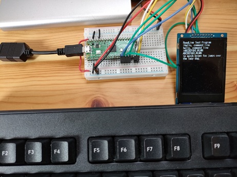
You can't see it in the photo, but the cursor is blinking properly.
USB Keyboard + OLED (SSD1306)
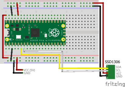
Connect the USB keyboard using a microB-TypeA adapter to the USB port. The OLED used is SSD1306.
The breadboard wiring image is shown below. Note that the 5V power is connected to the Pico board's VBUS (pin 40).
Add the following lines to the end of CMakeLists.txt:
target_link_libraries(cmdedit-display-test jxglib_USBHost jxglib_Display_SSD1306)
add_subdirectory(${CMAKE_CURRENT_LIST_DIR}/../pico-jxglib pico-jxglib)
jxglib_configure_USBHost(cmdedit-display-test CFG_TUH_HID 3)
Edit the source file as follows:
#include <stdio.h>
#include "pico/stdlib.h"
#include "jxglib/USBHost/HID.h"
#include "jxglib/Display/SSD1306.h"
#include "jxglib/Font/shinonome12.h"

using namespace jxglib;

Display::Terminal terminal;

int main()
{
    ::stdio_init_all();
    USBHost::Initialize();
    USBHost::Keyboard keyboard;
    ::i2c_init(i2c0, 400 * 1000);
    GPIO4.set_function_I2C0_SDA().pull_up();
    GPIO5.set_function_I2C0_SCL().pull_up();
    Display::SSD1306 display(i2c0, 0x3c);
    display.Initialize();
    terminal.SetFont(Font::shinonome12)
        .AttachDisplay(display).AttachKeyboard(keyboard);
    terminal.Println("ReadLine Test Program");
    for (;;) {
        char* str = terminal.ReadLine(">");
        terminal.Printf("%s\n", str);
    }
}
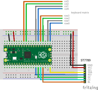
GPIO Keyboard Matrix + TFT LCD (ST7789)
Connect a keyboard matrix to the GPIO. Here, we use a 4x4 matrix type that can be easily obtained from Amazon, etc.
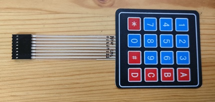
The breadboard wiring image is shown below.
Add the following lines to the end of CMakeLists.txt:
target_link_libraries(cmdedit-display-test jxglib_Display_ST7789)
add_subdirectory(${CMAKE_CURRENT_LIST_DIR}/../pico-jxglib pico-jxglib)
Edit the source file as follows:
#include <stdio.h>
#include "pico/stdlib.h"
#include "jxglib/Display/ST7789.h"
#include "jxglib/Font/shinonome16.h"

using namespace jxglib;

Display::Terminal terminal;

int main()
{
    ::stdio_init_all();
    GPIO::KeyboardMatrix keyboard;
    const Keyboard::KeySet keySetTbl[] = {
        VK_1,    VK_2, VK_3,     VK_BACK,
        VK_4,    VK_5, VK_6,     VK_UP,
        VK_7,    VK_8, VK_9,     VK_DOWN,
        VK_LEFT, VK_0, VK_RIGHT, VK_RETURN,
    };
    const GPIO::KeyRow keyRowTbl[] = { GPIO16, GPIO17, GPIO18, GPIO19 };
    const GPIO::KeyCol keyColTbl[] = {
        GPIO20.pull_up(), GPIO21.pull_up(), GPIO26.pull_up(), GPIO27.pull_up()
    };
    keyboard.Initialize(keySetTbl,
        keyRowTbl, count_of(keyRowTbl),
        keyColTbl, count_of(keyColTbl), GPIO::LogicNeg);
    ::spi_init(spi1, 125 * 1000 * 1000);
    GPIO14.set_function_SPI1_SCK();
    GPIO15.set_function_SPI1_TX();
    Display::ST7789 display(spi1, 240, 320, {RST: GPIO10, DC: GPIO11, CS: GPIO12, BL: GPIO13});
    display.Initialize(Display::Dir::Rotate0);
    terminal.SetFont(Font::shinonome16)
        .AttachDisplay(display).AttachKeyboard(keyboard);
    terminal.Println("ReadLine Test Program");
    for (;;) {
        char* str = terminal.ReadLine(">");
        terminal.Printf("%s\n", str);
    }
}
Some keyboard matrices have diodes for preventing ghosting, and some do not. If your matrix has diodes, change the code as follows depending on the diode polarity:
- If polarity is col → row: Set the GPIOs in
keyColTbltopull_up(), and set the last argument ofkeyboard.Initialize()toGPIO::LogicNeg. - If polarity is row → col: Set the GPIOs in
keyColTbltopull_down(), and set the last argument ofkeyboard.Initialize()toGPIO::LogicPos.
If there are no diodes, either way is fine.
Using Serial::Terminal
Connect the Pico board to a PC via a serial line.
Creating a Project for Serial::Terminal
From the VSCode command palette, run >Raspberry Pi Pico: New Pico Project and create a project with the following settings. For details on creating a Pico SDK project, building, and writing to the board, see "Getting Started with Pico SDK".
- Name ... Enter the project name. In this example, enter
cmdedit-serial-test. - Board type ... Select the board type.
- Location ... Select the parent directory where the project directory will be created.
- Stdio support ... Select the port (UART or USB) to connect Stdio.
- Code generation options ... Check
Generate C++ code
Assume the project directory and pico-jxglib are arranged as follows:
Connecting to the Host PC via Stdio
Connect the Pico board to the host PC via UART or USB (see here for details).
Add the following lines to the end of CMakeLists.txt:
target_link_libraries(cmdedit-serial-test jxglib_Serial)
add_subdirectory(${CMAKE_CURRENT_LIST_DIR}/../pico-jxglib pico-jxglib)
Edit the source file as follows:
#include <stdio.h>
#include "pico/stdlib.h"
#include "jxglib/Serial.h"

using namespace jxglib;

Serial::Terminal terminal;

int main()
{
    ::stdio_init_all();
    terminal.Initialize();
    terminal.AttachPrintable(Stdio::Instance).AttachKeyboard(Stdio::GetKeyboard());
    terminal.Println("ReadLine Test Program");
    for (;;) {
        char* str = terminal.ReadLine("> ");
        terminal.Printf("%s\n", str);
    }
}
You can edit the command line input from the host PC's terminal software.
-
A socket interface is planned to be added in the future. ↩