Display - TFT LCD
About TFT LCD
When it comes to peripherals connected to a CPU, display-related devices are perhaps the most fun to play with. From a practical standpoint, the amount of information you can convey to users through text and graphics is outstanding. Among the many types of displays, TFT LCDs that can be connected to single-board microcontrollers via SPI interface are especially attractive due to their compact size and affordable price.
By the way, I mainly use Akizuki Denshi and Amazon to procure electronic components. I searched for "TFT LCD" on these shops and purchased the following devices:
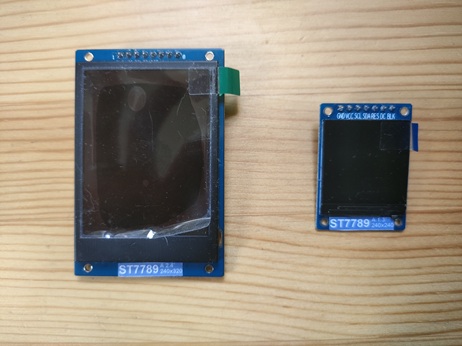
ST7789
The device on the left is 1.8 inches with 240x320 pixels, and the one on the right is 1.3 inches with 240x240 pixels. Both can be purchased for around 1,000 yen.
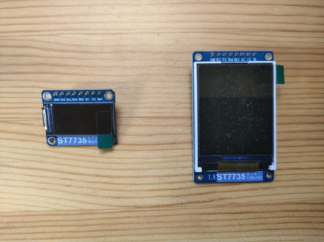
ST7735
The device on the left is 0.96 inches with 80x160 pixels, and the one on the right is 1.8 inches with 128x160 pixels. Both can be purchased for less than 1,000 yen.
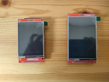
ILI9341/ILI9488
These are devices with touch screens. The left one is ILI9341, 2.8 inches with 240x320 pixels, and the right one is ILI9488, 3.5 inches with 320x480 pixels. The prices are about 1,500 yen and 2,500 yen, respectively.
The devices listed above have slight differences in initialization procedures, VRAM drawing direction, and pixel format, but their commands are almost the same. In this article, we will use pico-jxglib to draw image data and text on these devices.
Drawing on TFT LCD
Let's connect a TFT LCD and perform drawing operations.
From the VSCode command palette, run >Raspberry Pi Pico: New Pico Project and create a project with the following settings. For details on creating a Pico SDK project, building, and writing to the board, see "Getting Started with Pico SDK".
- Name ... Enter the project name. In this example, enter
lcdtest. - Board type ... Select the board type.
- Location ... Select the parent directory where the project directory will be created.
- Stdio support ... Select the port (UART or USB) to connect Stdio.
- Code generation options ... Check
Generate C++ code
Assume the project directory and pico-jxglib are arranged as follows:
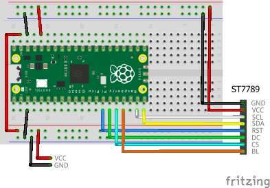
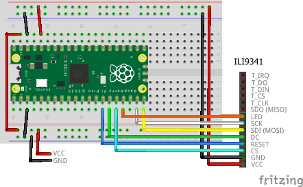
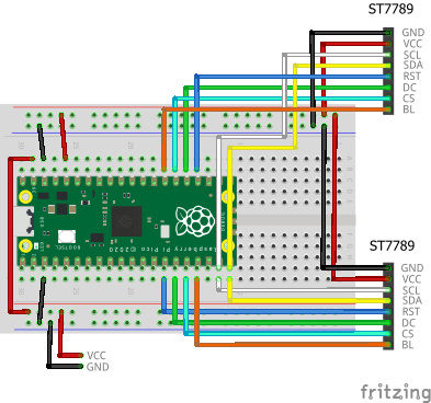
The breadboard wiring image is as follows:
Add the following lines to the end of CMakeLists.txt:
target_link_libraries(lcdtest jxglib_Display_ST7789 jxglib_DrawableTest)
add_subdirectory(${CMAKE_CURRENT_LIST_DIR}/../pico-jxglib pico-jxglib)
Edit the source file as follows:
#include <stdio.h>
#include "pico/stdlib.h"
#include "jxglib/Display/ST7789.h"
#include "jxglib/DrawableTest.h"

using namespace jxglib;

int main()
{
    ::stdio_init_all();
    ::spi_init(spi1, 125 * 1000 * 1000);
    GPIO14.set_function_SPI1_SCK();
    GPIO15.set_function_SPI1_TX();
    Display::ST7789 display(spi1, 240, 320, {RST: GPIO10, DC: GPIO11, CS: GPIO12, BL: GPIO13});
    display.Initialize(Display::Dir::Rotate0);
    DrawableTest::RotateImage(display);
    //DrawableTest::DrawString(display);
    //DrawableTest::DrawFonts(display);
}
The breadboard wiring image is as follows:
Add the following lines to the end of CMakeLists.txt:
target_link_libraries(lcdtest jxglib_Display_ST7789 jxglib_DrawableTest)
add_subdirectory(${CMAKE_CURRENT_LIST_DIR}/../pico-jxglib pico-jxglib)
Edit the source file as follows:
#include <stdio.h>
#include "pico/stdlib.h"
#include "jxglib/Display/ST7789.h"
#include "jxglib/DrawableTest.h"

using namespace jxglib;

int main()
{
    ::stdio_init_all();
    ::spi_init(spi1, 125 * 1000 * 1000);
    GPIO14.set_function_SPI1_SCK();
    GPIO15.set_function_SPI1_TX();
    Display::ST7789 display(spi1, 240, 240, {RST: GPIO10, DC: GPIO11, BL: GPIO13});
    display.Initialize(Display::Dir::Rotate0);
    DrawableTest::RotateImage(display);
    //DrawableTest::DrawString(display);
    //DrawableTest::DrawFonts(display);
}
The breadboard wiring image is as follows:
Add the following lines to the end of CMakeLists.txt:
target_link_libraries(lcdtest jxglib_Display_ST7735 jxglib_DrawableTest)
add_subdirectory(${CMAKE_CURRENT_LIST_DIR}/../pico-jxglib pico-jxglib)
Edit the source file as follows:
#include <stdio.h>
#include "pico/stdlib.h"
#include "jxglib/Display/ST7735.h"
#include "jxglib/DrawableTest.h"

using namespace jxglib;

int main()
{
    ::stdio_init_all();
    ::spi_init(spi1, 125 * 1000 * 1000);
    GPIO14.set_function_SPI1_SCK();
    GPIO15.set_function_SPI1_TX();
    Display::ST7735 display(spi1, 80, 160, {RST: GPIO10, DC: GPIO11, CS: GPIO12, BL: GPIO13});
    display.Initialize(Display::Dir::Rotate0);
    DrawableTest::RotateImage(display);
    //DrawableTest::DrawString(display);
    //DrawableTest::DrawFonts(display);
}
The breadboard wiring image is as follows:
Add the following lines to the end of CMakeLists.txt:
target_link_libraries(lcdtest jxglib_Display_ST7735 jxglib_DrawableTest)
add_subdirectory(${CMAKE_CURRENT_LIST_DIR}/../pico-jxglib pico-jxglib)
Edit the source file as follows:
#include <stdio.h>
#include "pico/stdlib.h"
#include "jxglib/Display/ST7735.h"
#include "jxglib/DrawableTest.h"

using namespace jxglib;

int main()
{
    ::stdio_init_all();
    ::spi_init(spi1, 125 * 1000 * 1000);
    GPIO14.set_function_SPI1_SCK();
    GPIO15.set_function_SPI1_TX();
    Display::ST7735::TypeB display(spi1, 128, 160, {RST: GPIO10, DC: GPIO11, CS: GPIO12, BL: GPIO13});
    display.Initialize(Display::Dir::Rotate0);
    DrawableTest::RotateImage(display);
    //DrawableTest::DrawString(display);
    //DrawableTest::DrawFonts(display);
}
The breadboard wiring image is as follows:
Add the following lines to the end of CMakeLists.txt:
target_link_libraries(lcdtest jxglib_Display_ILI9341 jxglib_DrawableTest)
add_subdirectory(${CMAKE_CURRENT_LIST_DIR}/../pico-jxglib pico-jxglib)
Edit the source file as follows:
#include <stdio.h>
#include "pico/stdlib.h"
#include "jxglib/Display/ILI9341.h"
#include "jxglib/DrawableTest.h"

using namespace jxglib;

int main()
{
    ::stdio_init_all();
    ::spi_init(spi1, 125 * 1000 * 1000);
    GPIO14.set_function_SPI1_SCK();
    GPIO15.set_function_SPI1_TX();
    Display::ILI9341 display(spi1, 240, 320, {RST: GPIO10, DC: GPIO11, CS: GPIO12, BL: GPIO13});
    display.Initialize(Display::Dir::Rotate0);
    DrawableTest::RotateImage(display);
    //DrawableTest::DrawString(display);
    //DrawableTest::DrawFonts(display);
}
The breadboard wiring image is as follows:
Add the following lines to the end of CMakeLists.txt:
target_link_libraries(lcdtest jxglib_Display_ILI9488 jxglib_DrawableTest)
add_subdirectory(${CMAKE_CURRENT_LIST_DIR}/../pico-jxglib pico-jxglib)
Edit the source file as follows:
#include <stdio.h>
#include "pico/stdlib.h"
#include "jxglib/Display/ILI9488.h"
#include "jxglib/DrawableTest.h"

using namespace jxglib;

int main()
{
    ::stdio_init_all();
    ::spi_init(spi1, 125 * 1000 * 1000);
    GPIO14.set_function_SPI1_SCK();
    GPIO15.set_function_SPI1_TX();
    Display::ILI9488 display(spi1, 320, 480, {RST: GPIO10, DC: GPIO11, CS: GPIO12, BL: GPIO13});
    display.Initialize(Display::Dir::Rotate0);
    DrawableTest::RotateImage(display);
    //DrawableTest::DrawString(display);
    //DrawableTest::DrawFonts(display);
}
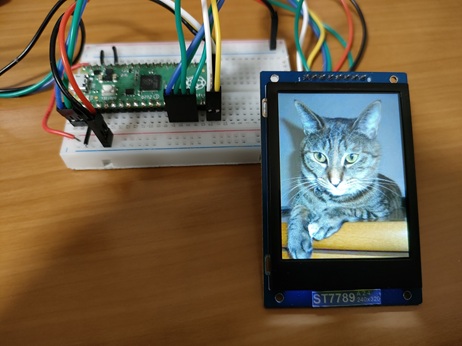
Uncomment the functions starting with DrawableTest:: and build, write, and run the program. The following will be displayed:
DrawableTest::RotateImage()is a test function that rotates and displays image data on the LCD. If you enter any key from a serial terminal connected via UART, the image will be rotated by 90 degrees and redrawn.
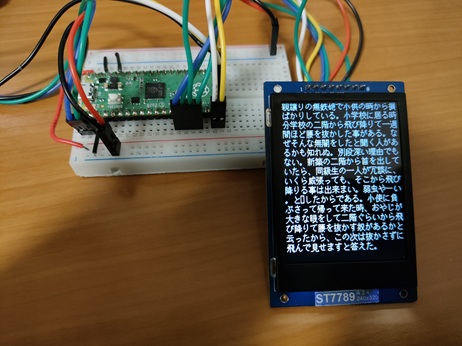
DrawablTest::DrawString()is a test function that displays Japanese text across the entire LCD screen. By operating from a serial terminal connected via UART, you can change the font type, font scaling, and line spacing.
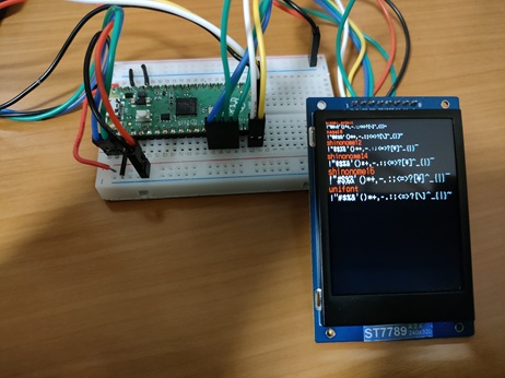
DrawablTest::DrawFonts()is a test function that displays strings in different fonts on the LCD.
Program Explanation
In the previous sample, we used test functions for demonstration, but this time let's use the raw API to see how each operation works. Rewrite the source file lcdtest.cpp as follows:
#include <stdio.h>
#include "pico/stdlib.h"
#include "jxglib/Display/ST7789.h"
#include "jxglib/sample/cat-240x320.h"
#include "jxglib/Font/shinonome16-japanese-level1.h"
using namespace jxglib;
int main()
{
// Initialize devices
::stdio_init_all();
::spi_init(spi1, 125 * 1000 * 1000);
GPIO14.set_function_SPI1_SCK();
GPIO15.set_function_SPI1_TX();
Display::ST7789 display(spi1, 240, 320, {RST: GPIO10, DC: GPIO11, CS: GPIO12, BL: GPIO13});
display.Initialize(Display::Dir::Rotate0);
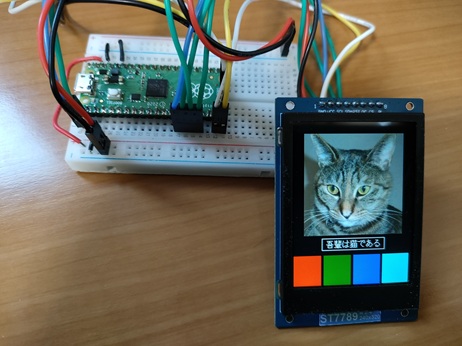
// Display items
display.DrawImage(20, 20, image_cat_240x320, {20, 20, 200, 200});
display.SetFont(Font::shinonome16);
const char* str = "I am a cat";
Size sizeStr = display.CalcStringSize(str);
int x = (display.GetWidth() - sizeStr.width) / 2, y = 230;
display.DrawString(x, y, str);
display.DrawRect(x - 8, y - 4, sizeStr.width + 8 * 2, sizeStr.height + 4 * 2, Color::white);
display.DrawRectFill(0, 260, 55, 60, Color::red);
display.DrawRectFill(60, 260, 55, 60, Color::green);
display.DrawRectFill(120, 260, 55, 60, Color::blue);
display.DrawRectFill(180, 260, 55, 60, Color::aqua);
}
The first half of the source file initializes the device.
This is a Pico SDK function. It initializes SPI1 with a clock of 125MHz.
Sets GPIO14 and GPIO15 to SPI1 SCK and TX (MOSI), respectively.
Creates an instance to operate the ST7789. Specify the SPI to connect, display size, and GPIOs to connect (RST: Reset, DC: Data/Command, CS: Chip Select, BL: Backlight).
Initializes the LCD and makes it ready for drawing. The argument specifies the LCD drawing direction as follows:
Display::Dir::Rotate0orDisplay::Dir::Normal... Draws in the normal directionDisplay::Dir::Rotate90... Rotates 90 degreesDisplay::Dir::Rotate180... Rotates 180 degreesDisplay::Dir::Rotate270... Rotates 270 degreesDisplay::Dir::MirrorHorz... Mirrors horizontallyDisplay::Dir::MirrorVert... Mirrors vertically
After this, you can perform drawing operations on the display instance.
Draws an image at the specified coordinates. The fourth argument specifies the clipping region within the image.
Specifies the font data Font::shinonome16 defined in the include file jxglib/Font/shinonome16-japanese-level1.h.
Calculates the size when drawing the string with the specified font.
Draws the string at the specified coordinates.
Draws a rectangle with specified coordinates, size, and color.
display.DrawRectFill(0, 260, 55, 60, Color::red);
display.DrawRectFill(60, 260, 55, 60, Color::green);
display.DrawRectFill(120, 260, 55, 60, Color::blue);
display.DrawRectFill(180, 260, 55, 60, Color::aqua);
Draws filled rectangles with specified coordinates, size, and color.
These are almost all the drawing functions provided by pico-jxglib. You might wonder about drawing circles or lines, but the requirements for graphic drawing are very high, and even if you struggle to make them yourself, they often end up being incomplete and not practical. Therefore, the policy is to leave such advanced drawing to specialized libraries. For example, if you need a Windows-like GUI with buttons or list boxes, there is an excellent library called LVGL. pico-jxglib provides adapters to bridge to such libraries.
Connecting Multiple LCDs
If the LCD device has a CS (Chip Select) pin, you can connect multiple devices in parallel to the same SPI interface.
Here, let's try connecting two ST7789s. The breadboard wiring image is as follows:
Rewrite the source file lcdtest.cpp as follows:
#include <stdio.h>
#include "pico/stdlib.h"
#include "jxglib/Display/ST7789.h"
#include "jxglib/Font/shinonome16-japanese-level1.h"
#include "jxglib/sample/cat-240x320.h"
#include "jxglib/sample/Text_Botchan.h"
using namespace jxglib;
int main()
{
::stdio_init_all();
::spi_init(spi1, 125 * 1000 * 1000);
GPIO14.set_function_SPI1_SCK();
GPIO15.set_function_SPI1_TX();
Display::ST7789 display1(spi1, 240, 320, {RST: GPIO10, DC: GPIO11, CS: GPIO12, BL: GPIO13});
Display::ST7789 display2(spi1, 240, 320, {RST: GPIO18, DC: GPIO19, CS: GPIO20, BL: GPIO21});
display1.Initialize(Display::Dir::Rotate0);
display2.Initialize(Display::Dir::Rotate90);
display1.DrawImage(0, 0, image_cat_240x320);
display2.SetFont(Font::shinonome16);
display2.DrawStringWrap(0, 0, Text_Botchan);
}
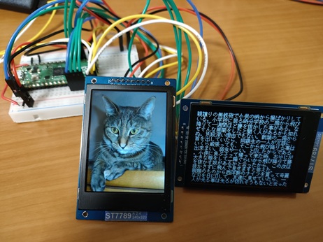
As long as you have enough GPIOs, you can connect as many LCDs as you want to the same SPI interface... or so you'd like to think, but if you connect too many, the signal waveform seems to deteriorate. I confirmed that you can connect up to four LCDs to the same SPI1, but if one of them is an ILI9341, it does not display.
-
At that time, I ran out of GPIOs, so I connected the BL (backlight) pin directly to VCC (3.3V). ↩