Connecting Multiple LCDs
If the LCD device has a CS (Chip Select) pin, you can connect multiple devices in parallel to the same SPI interface.
Wiring
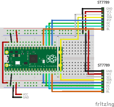
Here, let's try connecting two ST7789s. The breadboard wiring image is as follows:
Building and Flashing the Program
Create a new Pico SDK project named tftlcd-multi.
Create Pico SDK Project
- In VSCode, run
>Raspberry Pi Pico: New Pico Projectin the command palette. -
In the dialog below, select
C/C++.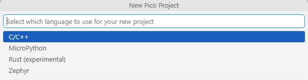
-
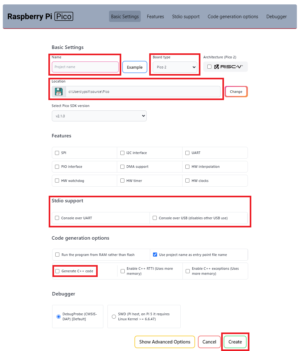
Create a project with the following settings:
- Name ... Enter the project name.
- Board type ... Select your board type.
- Location ... Select the parent directory where the project directory will be created.
- Stdio support ... Leave
Console over USBunchecked when you use LABOPlatform or other USB features because they conflict with each other. You can enable it by editing theCMakeLists.txtfile later. - Code generation options ... Check
Generate C++ code.
Open Existing Pico SDK Project
Open the project folder in VSCode using one of the following methods:
- In a command prompt, change the current directory to the project folder and execute
code .. -
In a Explorer, choose the project folder, push
Alt+Dto focus the address bar, and executecode ..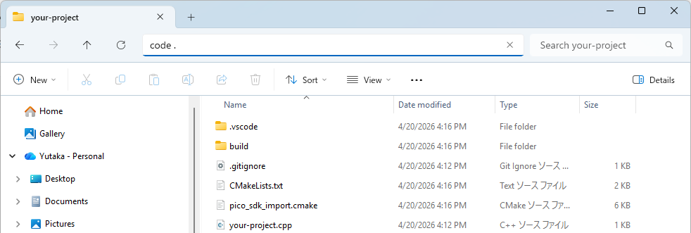
If the folder is already prepared as a Pico SDK project, just proceed with editing and building the project.
If not, you will see the following message at the bottom right corner of VSCode.
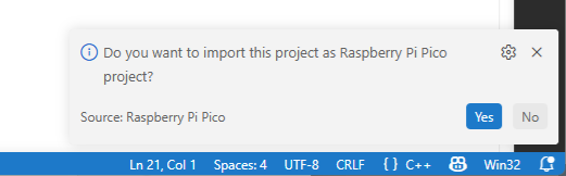
Click Yes and you will see the following window.
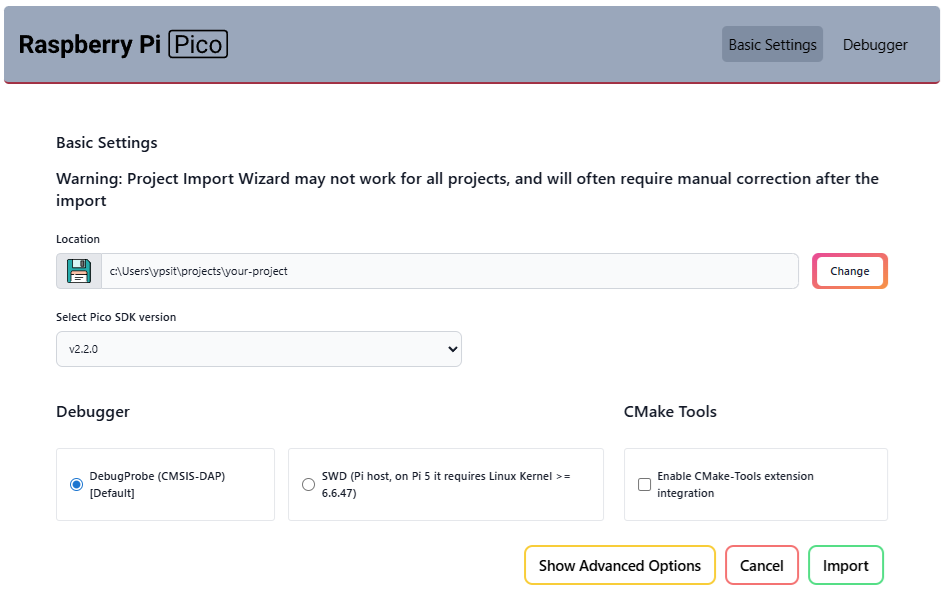
Click Import and the project will be prepared as a Pico SDK project.
When the Do you want to import this project as Raspberry Pi Pico project? message disappears before you click Yes, you can reveal it by clicking the icon  at the bottom right corner of VSCode.
Clone the pico-jxglib repository from GitHub so the direcory structure looks like this:
Clone the Repository
Change the current directory to the parent directory where you want to clone the pico-jxglib repository and run the following commands:
$ git clone https://github.com/ypsitau/pico-jxglib.git
$ cd pico-jxglib
$ git submodule update --init --recursive
pico-jxglib is updated almost daily. If you've already cloned it, run the following command in the pico-jxglib directory to get the latest version:
A directory from a Git repository can safely be moved to another location even after cloning.
Add the following lines to the end of CMakeLists.txt:
| CMakeLists.txt | |
|---|---|
Edit the source file as follows:
About Program
As long as you have enough GPIOs, you can connect as many LCDs as you want to the same SPI interface... or so you'd like to think, but if you connect too many, the signal waveform seems to deteriorate. I confirmed that you can connect up to four LCDs to the same SPI1, but if one of them is an ILI9341, it does not display.
-
At that time, I ran out of GPIOs, so I connected the BL (backlight) pin directly to VCC (3.3V). ↩