Observing PWM Signals
After clicking the Run button in PulseView to start capturing, run the following commands in your terminal software:
L:/>pwm 2,3,4 func:pwm freq:1000 counter:0
L:/>pwm2 duty:.2; pwm3 duty:.5; pwm4 duty:.8
L:/>pwm 2,3,4 enable
These commands set GPIO2, GPIO3, and GPIO4 to PWM function, set the frequency to 1kHz, set the duty cycles to 20%, 50%, and 80% respectively, and enable PWM.
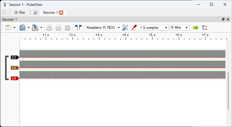
Click the Stop button in PulseView to stop capturing. The captured waveforms will be displayed as shown below.
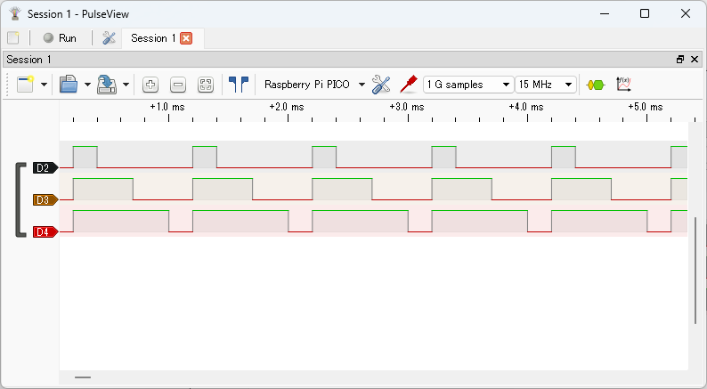
The image below shows a zoomed-in view of the beginning of the signal waveform.
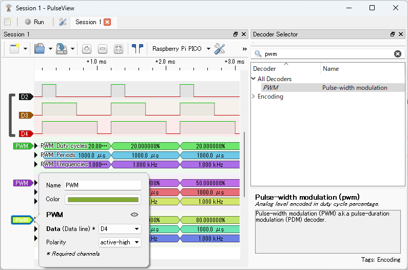
Display the Decoder Selector pane, enter pwm in the search box, and double-click PWM in the list to add PWM decoders to the waveform (add three in total). Left-click the PWM label in the signal name to open the protocol decoder parameter dialog, and set the Data field to D2, D3, and D4 for each decoder.
Close the dialog to see the decoded PWM results.
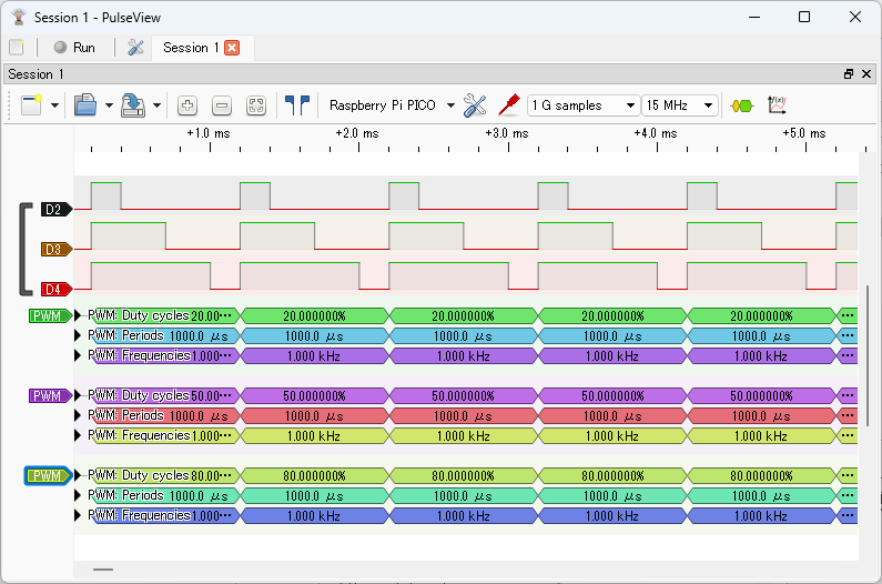
You can see PWM signals with duty cycles of 20%, 50%, and 80% at a frequency of 1.0kHz.
For more details on PWM operation with pico-jxgLABO, see the following article: