Device Connection
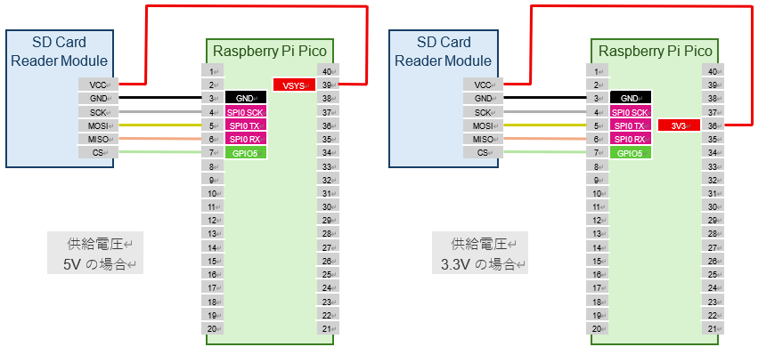
The SD card reader module is connected via the SPI interface. You can use either SPI0 or SPI1 on the Pico board, and the pin layout can be freely set with commands. Here, we use SPI0 and connect as follows:
| SD Card Reader Module | Pico Pin No. | GPIO | Function |
|---|---|---|---|
| VCC | 39 or 36 | VSYS or 3V3 | |
| GND | 3 | GND | |
| SCK | 4 | GPIO2 | SPI0 SCK |
| MOSI | 5 | GPIO3 | SPI0 TX (MOSI) |
| MISO | 6 | GPIO4 | SPI0 RX (MISO) |
| CS | 7 | GPIO5 | SIO |
Warning
Be careful where you connect the VCC of the SD card reader module, depending on the supply voltage: - For 5V supply, connect to VSYS (pin 39) on the Pico board. If you connect to 3V3, the voltage drop across the module's regulator will prevent proper operation. - For 3.3V supply, connect to 3V3 (pin 36) on the Pico board. If you connect to VSYS, the SD card may be damaged.
The wiring diagram is shown below. There are multiple GND pins on the Pico board, so you can connect to any of them.
Run the following command to set the GPIO assignment for SPI0 to GPIO2 (SPI0 SCK), GPIO3 (SPI0 TX), and GPIO4 (SPI0 RX). The appropriate function assignment is done automatically, so the order does not matter.
Run the following command to set the SPI interface for the SD card to SPI0, the CS pin to GPIO5, and the drive name to M:
This completes the SD card setup.