Observing SPI Signals
After clicking the Run button in PulseView to start capturing, run the following command in your terminal software:
This command assigns GPIO2 and GPIO3 to SPI0 MOSI and SCK, and sends data from 0 to 255.
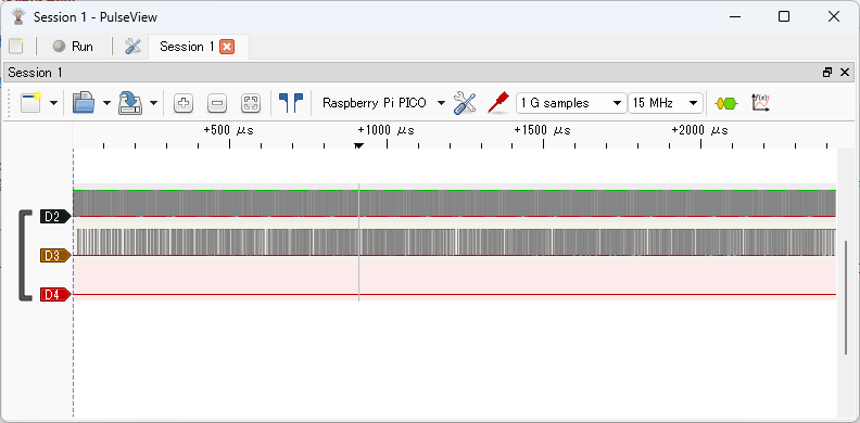
Click the Stop button in PulseView to stop capturing. The captured waveforms will be displayed as shown below. D2 is GPIO2 (SPI0 SCK), and D3 is GPIO3 (SPI0 MOSI).
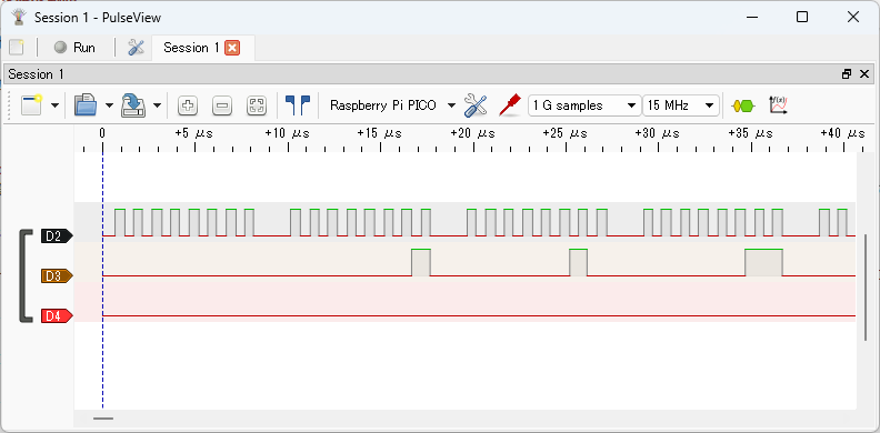
The image below shows a zoomed-in view of the beginning of the signal waveform.
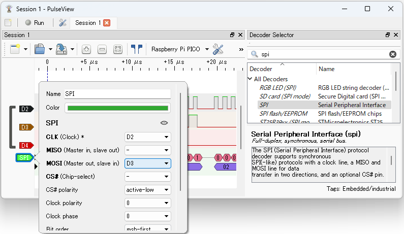
Display the Decoder Selector pane, enter spi in the search box, and double-click SPI in the list to add the SPI decoder to the waveform. Left-click the SPI label in the signal name to open the protocol decoder parameter dialog, and set CLK to D2 and MOSI to D3.
Close the dialog to see the decoded SPI results.
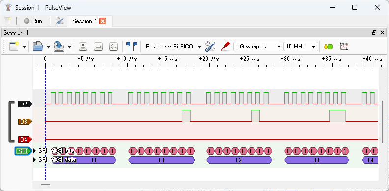
You can see that data from 0 to 255 is sent on SPI MOSI.