Shell with OLED and USB Keyboard
The shell can work with an OLED display as an output device and a USB keyboard as an input device. This allows you to use the shell without connecting the Pico board to a computer, making it more portable and versatile.
Wiring
The breadboard wiring image is as follows:
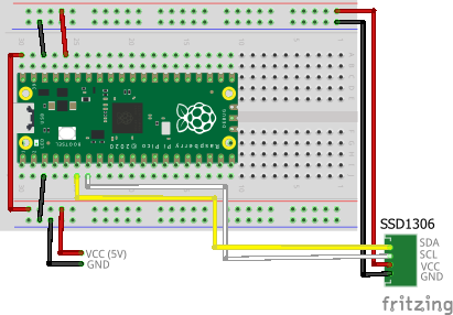
This circuit requires an external power supply to power the board and the USB keyboard. Make sure to connect the VCC to pin 40 (VBUS) that is directly connected to the USB power, not to pin 39 (VSYS).
Building and Flashing the Program
Here, we will create a sample program that implements a custom command named argtest. It displays the contents of the arguments passed to it.
Create a new Pico SDK project named shell-with-oled-usbkey.
Create Pico SDK Project
- In VSCode, run
>Raspberry Pi Pico: New Pico Projectin the command palette. -
In the dialog below, select
C/C++.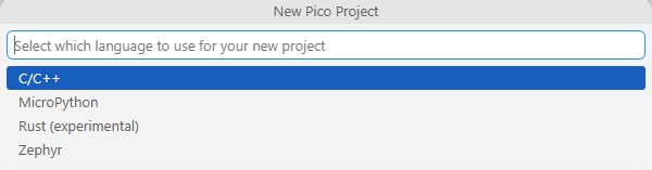
-
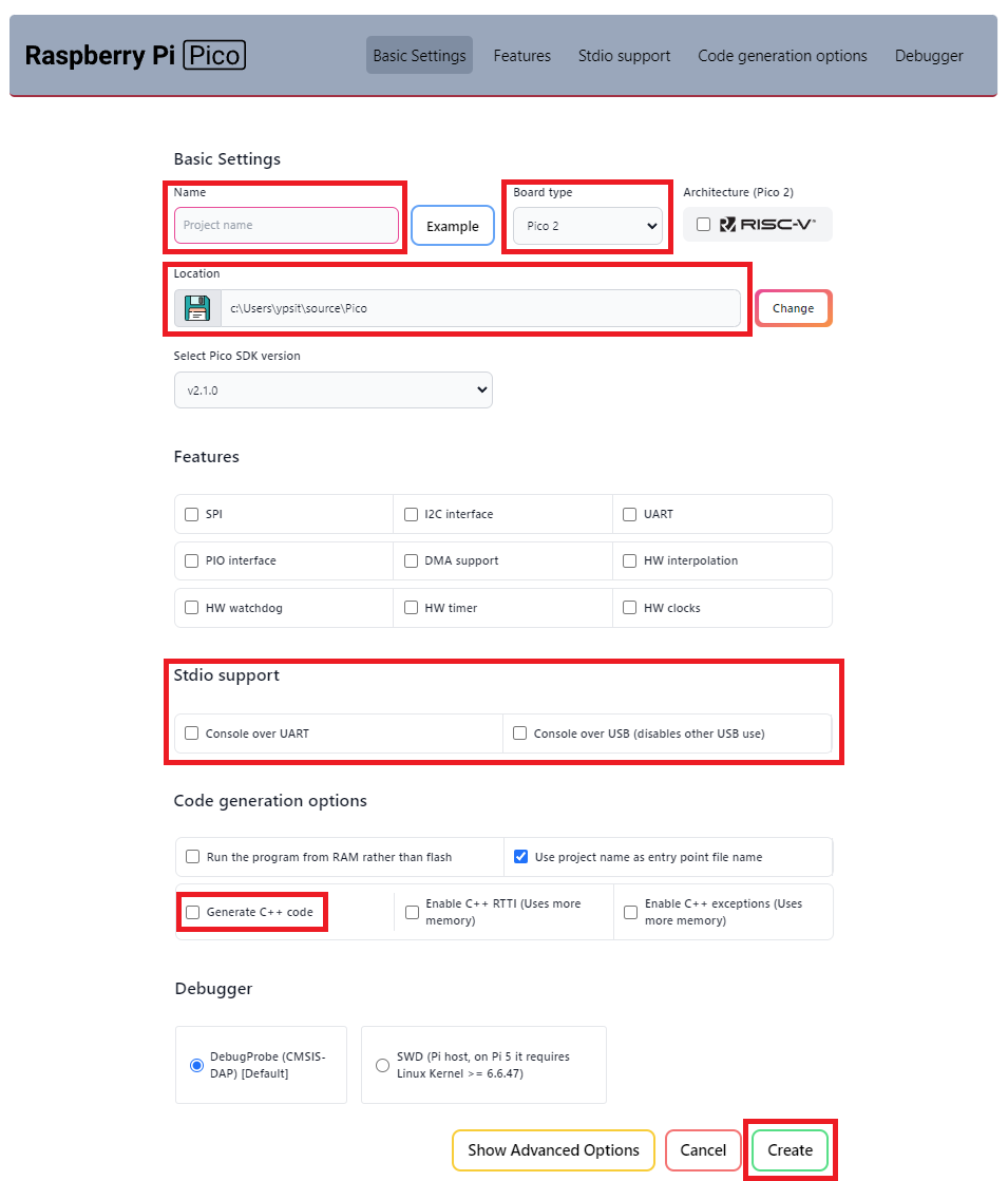
Create a project with the following settings:
- Name ... Enter the project name.
- Board type ... Select your board type.
- Location ... Select the parent directory where the project directory will be created.
- Stdio support ... Leave
Console over USBunchecked when you use LABOPlatform or other USB features because they conflict with each other. You can enable it by editing theCMakeLists.txtfile later. - Code generation options ... Check
Generate C++ code.
Open Existing Pico SDK Project
Open the project folder in VSCode using one of the following methods:
- In a command prompt, change the current directory to the project folder and execute
code .. -
In a Explorer, choose the project folder, push
Alt+Dto focus the address bar, and executecode ..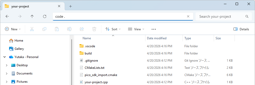
If the folder is already prepared as a Pico SDK project, just proceed with editing and building the project.
If not, you will see the following message at the bottom right corner of VSCode.
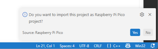
Click Yes and you will see the following window.
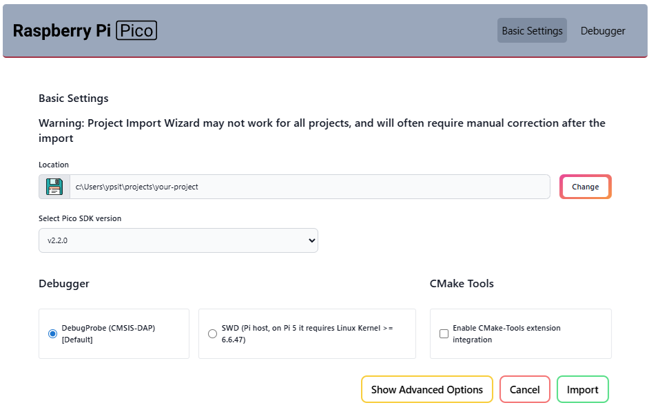
Click Import and the project will be prepared as a Pico SDK project.
When the Do you want to import this project as Raspberry Pi Pico project? message disappears before you click Yes, you can reveal it by clicking the icon  at the bottom right corner of VSCode.
Clone the pico-jxglib repository from GitHub so the direcory structure looks like this:
├── pico-jxglib/
└── shell-with-oled-usbkey/
    ├── CMakeLists.txt
    ├── shell-with-oled-usbkey.cpp
    └── ...
Clone the Repository
Change the current directory to the parent directory where you want to clone the pico-jxglib repository and run the following commands:
$ git clone https://github.com/ypsitau/pico-jxglib.git
$ cd pico-jxglib
$ git submodule update --init --recursive
pico-jxglib is updated almost daily. If you've already cloned it, run the following command in the pico-jxglib directory to get the latest version:
A directory from a Git repository can safely be moved to another location even after cloning.
Add the following lines to the end of CMakeLists.txt:
| CMakeLists.txt | |
|---|---|
Edit shell-with-oled-usbkey.cpp as follows:
Build and flash the program to the board.
Build and Flash
The simplest way to build and flash the program is to use the UF2 file generated by the build process. Pico board, a USB cable, and a computer are all you need to get started. Here are the steps to build and flash the program:
-
Pressing
F7on VSCode will build the project. If this is the first time you build the project, you will see the dialog shown below. SelectPico Using compilers: ...and the build process will start.
-
After building, you can find the generated UF2 file in the
builddirectory. - Connect your Pico to the computer using a USB cable while holding the BOOTSEL button, and it will appear as a mass storage device. Copy the generated UF2 file to this device to flash it. No need to mind the destination directory, just copy it to the root directory of the device.
If you have a debug probe like this, you can also flash the program using OpenOCD and GDB. This is the recommended method for development, as it allows you to debug the program while running it on the board!